Modify Single Equipment
The Modify Single Equipment function is used to change a single equipment unit.
Note: Equipment units that are in “conflict” require solution of all conflicts when making changes. Making changes to one element can cause conflicts in another related element. Read through all of the errors, as they can be related to a single input field. Unresolved conflicts can result in Umler enforcing AAR business rules against the equipment. Refer to the Umler Data Specification Manual for acceptable values for fields and assistance in resolving conflicts, as well as descriptions of conflict-related business rules.
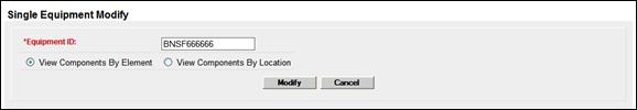
1. Select Maintenance>Add/Change/Delete>Modify Single Equipment. The Modify Single Equipment page is displayed (Exhibit 108).
Exhibit 108. Single Equipment Modify
2. Type the Equipment ID of the equipment to be modified.
Note: If Modify was selected from a query result, Single Equipment Modify - Components by Element View page is displayed (Exhibit 109).
3. (Optional) Select the View Components by Location radio button. Component and Location diagrams and descriptions are provided in the Umler Data Specification Manual (accessed from the upper right Help link).
4. Select Modify. The Single Equipment Modify - Components by Element View page is displayed (Exhibit 109).
Exhibit 109. Single Equipment Modify - Components by Element View
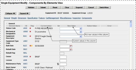
5. Select or type values in the fields that require changing.
Note: For element field help, select the ID link for the field. See Field Help.
If viewing components in location view, or if the Switch View button is selected, some additional fields are available (Exhibit 110).
Exhibit 110. Single Equipment Modify - Components By Location View
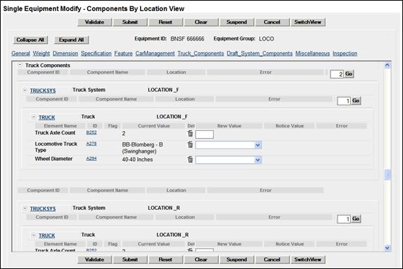
In Exhibit 110, the Truck System shows one component in the box at the right, and existing values are shown in the four fields under Location_F.
a. To add another Truck, increment the 1 in the box to 2, and select Go. A new Location with open fields is provided (Exhibit 111).
Exhibit 111. After Adding Second Truck Component
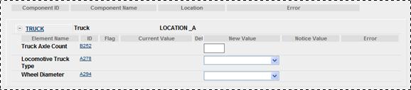
It is LOCATION_A and has the same elements as LOCATION _F, but no values.
b. Add the new values as appropriate.
6. When all input is complete, select Validate. The system validates entries against railroad business rules and acceptable values. If errors are found, an error message appears under the page title and any element-specific error messages are displayed in the error column beside the element.
7. Correct errors and revalidate as described in Step 9.
8. (Optional) Suspend the modify task for later completion as described in the Note.
9. Select Submit to modify equipment unit. The Equipment updates submitted to the system Success page is displayed (similar to Exhibit 103).
![]()
Legal Notices | Terms of Service | Umler Reference Materials
© 2013 Railinc Corp. All rights reserved.